
- English
- Español
- Português
- русский
- Français
- 日本語
- Deutsch
- tiếng Việt
- Italiano
- Nederlands
- ภาษาไทย
- Polski
- 한국어
- Svenska
- magyar
- Malay
- বাংলা ভাষার
- Dansk
- Suomi
- हिन्दी
- Pilipino
- Türkçe
- Gaeilge
- العربية
- Indonesia
- Norsk
- تمل
- český
- ελληνικά
- український
- Javanese
- فارسی
- தமிழ்
- తెలుగు
- नेपाली
- Burmese
- български
- ລາວ
- Latine
- Қазақша
- Euskal
- Azərbaycan
- Slovenský jazyk
- Македонски
- Lietuvos
- Eesti Keel
- Română
- Slovenski
- मराठी
- Srpski језик
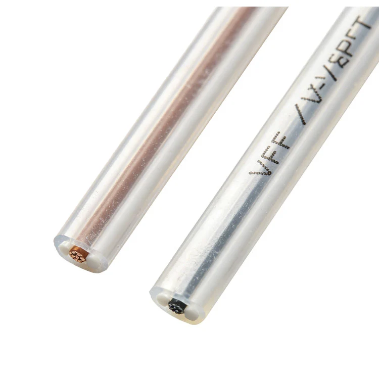
Japanese Standard Flat Twin Wire
For applications requiring reliable, space-saving, and safe electrical connections, the Japanese Standard Flat Twin Wire represents a pinnacle of design and engineering. This specialized cable, adhering to stringent Japanese manufacturing standards (JIS C 3306), is engineered for durability and consistent performance in demanding environments. Its flat, parallel twin-core configuration is ideal for wiring within appliances, control panels, lighting fixtures, and internal machinery where a low-profile, flexible solution is paramount. A key variant within this category is the Japanese VFF Flat Twin Core Wire, known for its fine-stranded conductors offering superior flexibility. For scenarios demanding robust insulation, the Japanese VHF PVC Insulated Flat Cable provides enhanced protection. The standard offering, often referred to as PVC Insulated Japanese Flat Twin Wire, combines a polyvinyl chloride sheath with parallel conductors for general-purpose use. Collectively, these products exemplify the Japanese Style Double Core Flat Wire approach, prioritizing precision, safety (typically rated 300V), and efficient use of space.
The Japanese Standard Flat Twin Wire is characterized by a set of precise technical parameters that define its performance and suitability for specific applications. The construction typically involves two parallel tinned copper conductors, which provide excellent conductivity and corrosion resistance. These conductors are individually insulated with a high-grade PVC compound, color-coded (usually red and white or black and white) for easy polarity identification during installation. The insulated cores are then laid parallel and sheathed together in a final layer of durable PVC, forming the characteristic flat profile. This design ensures not only physical protection but also enhances heat dissipation. Key specifications include the conductor size (cross-sectional area), overall dimensions, electrical ratings, and temperature range. The following table and list detail the standard specifications for common models of this wire.
Key Product Specifications
- Standard Compliance: Manufactured to JIS C 3306 standards.
- Conductor: Tinned annealed copper, stranded for flexibility.
- Insulation: High-quality Polyvinyl Chloride (PVC).
- Sheath/Jacket: Tough, durable PVC outer sheath.
- Voltage Rating: 300V.
- Temperature Rating: -10°C to +60°C for general use.
- Flame Retardancy: Compliant with standard flame-retardant requirements.
- Core Identification: Insulation is color-coded for easy polarity distinction.
| Model / Size (mm²) | Conductor Structure (No./mm) | Finished Outer Dimensions (Approx. mm) | Max. DC Resistance at 20°C (Ω/km) | Current Rating (A) * |
|---|---|---|---|---|
| 0.5 sq mm | 20/0.18 | 2.0 x 4.0 | 39.0 | 7 |
| 0.75 sq mm | 30/0.18 | 2.2 x 4.4 | 26.0 | 12 |
| 1.25 sq mm | 50/0.18 | 2.7 x 5.4 | 15.6 | 17 |
| 2.0 sq mm | 37/0.26 | 3.2 x 6.4 | 9.74 | 23 |
* Current rating is indicative and can vary based on installation conditions and ambient temperature. Always consult relevant engineering guidelines for specific applications.
Related Products
Hot Products
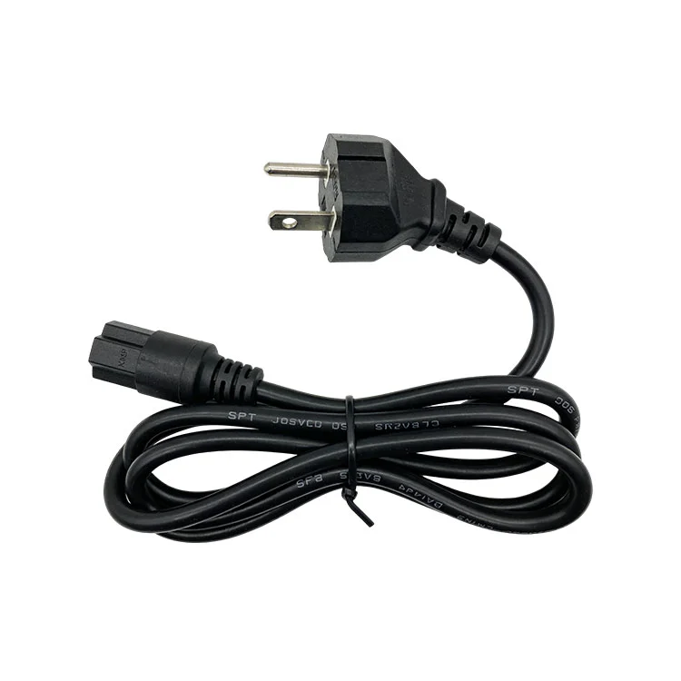
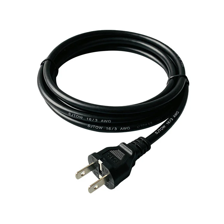
American Standard SPT Power Cord
The American standard SPT power cord supplied by Shujie Electrical manufacturer is a dedicated power cord specifically designed for North America and regions that conform to American standards. It is professionally developed and produced by us, and strictly follows the strict UL (American Insurance Laboratory) and CSA (Canadian Standards Association) safety standards throughout the process. It fully complies with American electrical compliance requirements.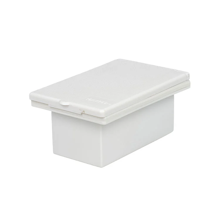
EU IP44 Waterproof RV Socket Box
The EU IP44 waterproof RV socket box manufactured by Shujie Electrical's supplier is a professional protective device specifically designed for outdoor power usage scenarios in recreational vehicles. It is crafted from durable engineering materials and can easily withstand the variable outdoor conditions, including intense sunlight, humid moisture, and flying sand. It maintains stable protective performance in all these circumstances.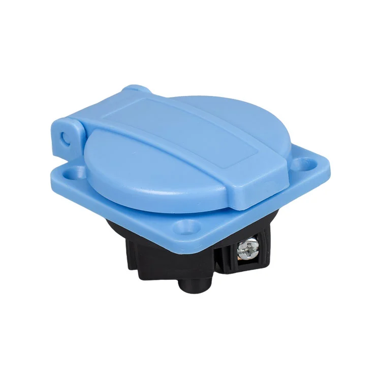
Extension Cord Socket
The China Extension Cord Socket supplied by Shujie Electrical Manufacturer is a practical power accessory that combines portability and protection. It is specially designed for scenarios that require flexible power access. It features a compact integrated structure and a protective design with a flip cover, which not only effectively prevents dust and water splashes but also makes it convenient for storage and carrying.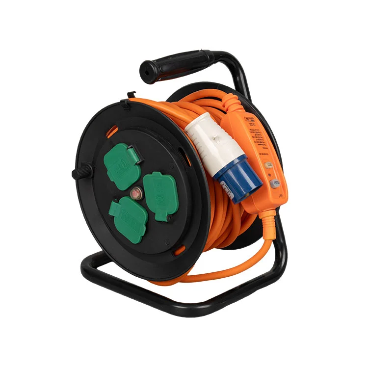
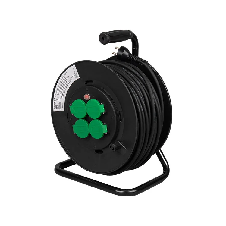
Industrial Cable Reel
This Industrial Cable Reel by Shujie is suitable for both home and office settings, offering a reliable and practical power management option. Constructed from high-quality fire-resistant materials, its sturdy and long-lasting design prevents cable wear and tangling. The design of the reel ensures cables are organized neatly and can be unwound easily, keeping the space tidy. This product, directly sold by a professional export factory, complies with international safety standards and is appropriate for both export sales and wholesale markets.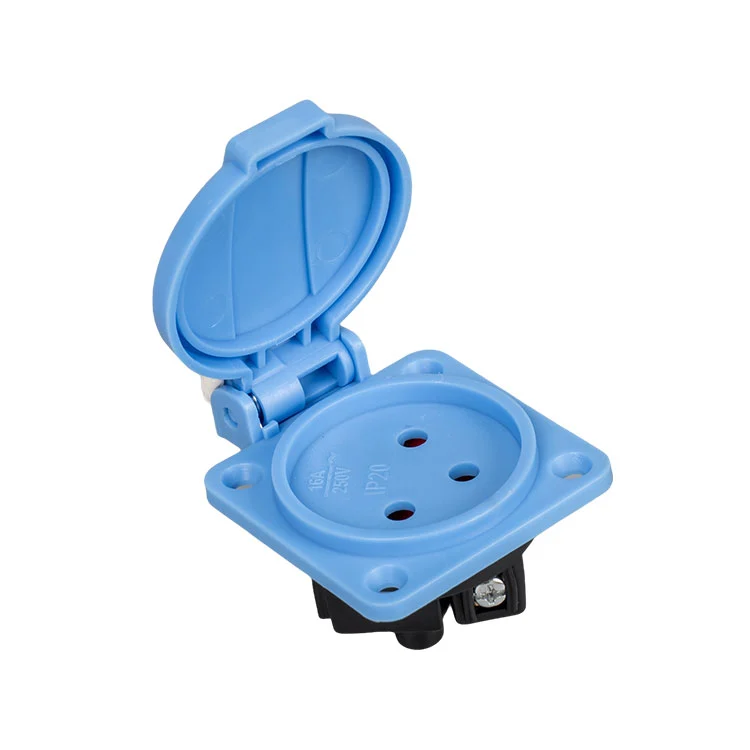
Portable EU Socket
Cixi Shujie Import & Export Co., Ltd. is an Portable EU Socket manufacturer, we specialized on the production and export of Portable EU Sockets, We offer you reliable, safe, and high quality power solution for home, office, and travel use. They are made according to European standards, these portable sockets can make sure the connections are safe and flexible wherever people need electricity.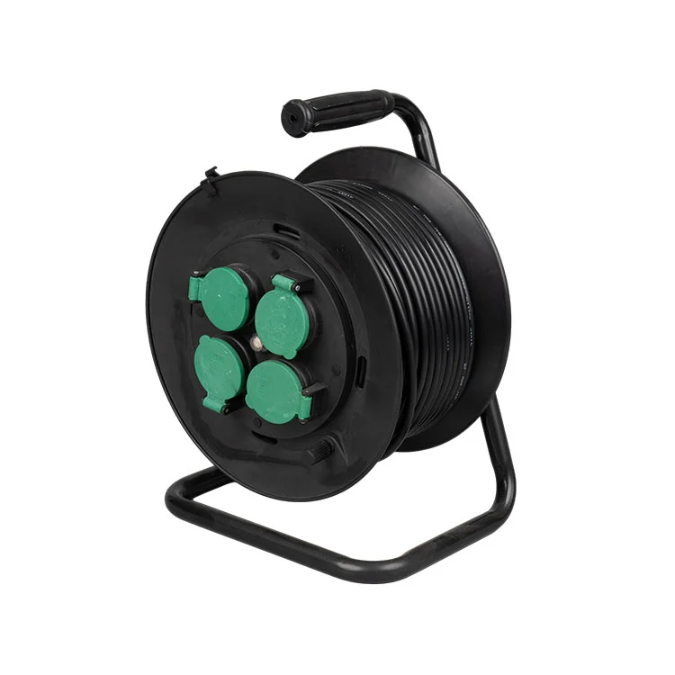
Household Reel
The China Hhousehold Reel, produced by Shujie Electrical manufacturer, is a safe power collection device specially designed for daily household power usage scenarios. It differs from ordinary reel products and industrial models. Its main selling points are "safe adaptation for home use, and convenient storage without causing clutter". It eliminates complex designs and adopts a simple and compact body shape, which does not occupy space in the home. It is equipped with flexible extendable cables and multiple universal sockets. It can solve the problem of limited power collection range in the home and ensure the safety of home power usage by having a built-in leakage protection device.
- Related Blog
- Reviews
